Threaded Rod, also referred to as Threaded Bar, are Steel Rods with continuous threads along their entire length. Unlike regular screws, they lack a forged head or shank, resulting in a consistent diameter throughout the entire Threaded Rod.
What are they used for?
Threaded rods are frequently used in construction, serving as anchor points for joining multiple components securely. Their extended length and increased rigidity, compared to standard bolts, make them ideal for applications demanding strength and stability, (e.g. bridge construction). Threaded rods are also valuable in scenarios subject to frequent vibrations, like engine blocks, as well as for purposes like HVAC and plumbing hangers.

Types of threaded rod
Threaded rod comes in different types of steel, finishes and thread types. Milsons offers threaded rod in four categories:
- Metric: Standard metric threads ranging from M3 to M56.
- Metric Fine: Same as above, but with finer thread pitch.
- Imperial UNC: Standard imperial coarse threads, ranging from 5/16 to 1 ½”
- Imperial UNF: Same as above, but with finer thread pitch.
They also exist in different materials and finishes, and each one is suited for different applications. Milsons offers the following finishes:
- Plain: Plain threaded rod is a common choice, frequently employed in construction projects where the materials remain concealed within the structure, protected from the elements.
- Zinc: Zinc-plated threaded rod introduces corrosion resistance, making it suitable for environments exposed to weather or chemicals.
- Yellow zinc: Similar to Zinc Plating, but featuring a yellow chromate top coating, Yellow Zinc offers improved durability and corrosion resistance. The robust look of the yellow chromate is often more appealing in industries such as electrical and plumbing, where fittings are exposed.
- Galvanised: Galvanised finishes offer superior corrosion resistance, compared to zinc plating, making them ideal for outdoor applications.
- Stainless steel: Stainless Steel Threaded Rods offer excellent durability and corrosion resistance, making them extremely beneficial for use in outdoor and marine applications. It’s strength enables it to withstand a great deal of tension without breaking or bending.
Applications of threaded rods and how to choose:
- Construction:
In construction, threaded rod frequently serves as essential structural supports, facilitating robust connections between materials such as wood, metal, and concrete. - Machinery and Equipment:
Threaded rods also play a pivotal role in heavy machinery and equipment, where they secure foundations and ensure precise positioning for various components. - Manufacturing:
In the manufacturing sector, threaded rod is often incorporated into jigs, fixtures and other types of manufacturing equipment. Their high level of strength allows for easy adjustments to fit the requirements of the equipment. - Electrical Applications:
Electricians frequently use Threaded Rod to support cable trays, wiring and various other electrical elements. Additionally, it can serve as an effective grounding rod, ensuring a stable connection to earth. - Automotive Applications:
Threaded Rod plays a crucial role in the automotive industry, servicing as essential components in engine and transmission mounts, suspension parts and drivetrain elements.
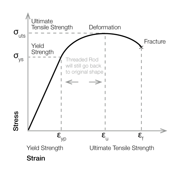
Tensile Strength
The graph shows a typical stress-strain curve of Threaded Rod. As the Threaded Rod is subjected to increasing tensile force, stresses increase beyond the proportional limit. At this point, the rod starts stretching more than the stress applied to it. Although the proportionality of stress to strain is now lost, elasticity is not, and upon removal of the stress load, the threaded rod will still return back to its original dimensions.
Anywhere past this point, where the load is greater than the rod’s yield strength, permanent deformation will occur, and the Threaded Rod will no longer hold its original form.
It is important to understand the final load or force that Threaded Rod can withstand before it fractures to determine the strength and durability of the metal component. For more information, refer to the tables below.
Graph 1. Tensile Strength
Ultimate Tensile Loads for Metric Fasteners
Tables 1 and 2 below show the Ultimate Tensile Loads for standard metric bolts for both coarse and fine pitch threads. The values for the Ultimate Tensile Loads are based on the specifications provided in ISO 898 Part 1.
This standard lays out specifications for the mechanical and physical properties for metric threaded fasteners made from carbon and alloy steel tested within a temperature range of 10 °C to 35 °C.
Table 1. Minimum Ultimate Tensile Loads — ISO Metric Fine Thread
| Nominal Size | Pitch, mm (Fine) | Nominal Stress Area, mm2 | Minimum Tensile Load, N (Property Class 8.8) |
|---|---|---|---|
| M8 | 1.00 | 39.2 | 31360 |
| M10 | 1.00 | 64.5 | 49000 |
| M10 | 1.25 | 61.2 | 51600 |
| M12 | 1.25 | 92.1 | 70500 |
| M12 | 1.50 | 88.1 | 73700 |
| M14 | 1.50 | 125 | 100000 |
| M16 | 1.50 | 167 | 134000 |
| M18 | 1.50 | 216 | 179000 |
| M20 | 1.50 | 272 | 226000 |
| M22 | 1.50 | 333 | 276000 |
| M24 | 2.00 | 384 | 319000 |
| M27 | 2.00 | 496 | 412000 |
| M30 | 2.00 | 621 | 515000 |
| M33 | 2.00 | 761 | 632000 |
| M36 | 3.00 | 865 | 718000 |
| M39 | 3.00 | 1030 | 855000 |
Table 2. Minimum Ultimate Tensile Loads — ISO Metric Coarse Thread
| Minimal Ultimate Tensile Loads, N (Property classes 4.8 to 10.9) | |||||||
|---|---|---|---|---|---|---|---|
| Nominal Bolt Size | Pitch, mm (Coarse) | Nominal stress area, mm2 | 4.8 | 5.8 | 6.8 | 8.8 | 10.9 |
| M3 | 0.50 | 5.03 | 2110 | 2620 | 3020 | 4020 | 5230 |
| M3.5 | 0.60 | 6.78 | 2850 | 3530 | 4070 | 5420 | 7050 |
| M4 | 0.70 | 8.78 | 3690 | 4570 | 5270 | 7020 | 9130 |
| M5 | 0.80 | 14.2 | 5960 | 7380 | 8520 | 11350 | 14800 |
| M6 | 1.00 | 20.1 | 8440 | 10400 | 12100 | 161000 | 20900 |
| M7 | 1.00 | 28.9 | 12100 | 15000 | 17300 | 231000 | 30100 |
| M8 | 1.25 | 36.6 | 15400 | 19000 | 22000 | 292000 | 38100 |
| M10 | 1.50 | 58 | 24400 | 30200 | 34800 | 464000 | 60300 |
| M12 | 1.75 | 84.3 | 35400 | 43800 | 50600 | 67400 | 87700 |
| M14 | 2.00 | 115 | 48300 | 59800 | 69000 | 92000 | 120000 |
| M16 | 2.00 | 157 | 65900 | 81600 | 94000 | 125000 | 163000 |
| M18 | 2.50 | 192 | 80600 | 99800 | 115000 | 159000 | 200000 |
| M20 | 2.50 | 245 | 103000 | 127000 | 147000 | 203000 | 250000 |
| M22 | 2.50 | 303 | 127000 | 158000 | 182000 | 252000 | 315000 |
| M24 | 3.00 | 353 | 148000 | 184000 | 212000 | 293000 | 367000 |
| M27 | 3.00 | 459 | 193000 | 239000 | 275000 | 381000 | 477000 |
| M30 | 3.50 | 561 | 236000 | 292000 | 337000 | 466000 | 583000 |
| M33 | 3.50 | 694 | 292000 | 361000 | 416000 | 576000 | 722000 |
| M36 | 4.00 | 817 | 343000 | 425000 | 490000 | 678000 | 850000 |
| M39 | 4.00 | 976 | 410000 | 508000 | 586000 | 810000 | 1020000 |
Ultimate Tensile Loads For Imperial Fasteners
The minimum tensile loads for imperial threaded fasteners are based on the requirements set in the standard SAE J429. This standard covers the requirements for chemical and material properties for inch series bolts, studs and threaded fasteners made from steel. Tables 3 and 4 show the minimum ultimate tensile loads for UNC (coarse) and UNF (fine) threads.
Table 3. Minimum Tensile Load for Imperial Bolts (UNC)
| Nominal Size (in) | Stress area (in2) | Minimum Tensile Load (kN) | |
|---|---|---|---|
| Grade 5 | Grade 8 | ||
| 1/4 – 20 | 0.0318 | 16.9 | 21.1 |
| 5/16 – 18 | 0.0524 | 28.0 | 34.9 |
| 3/8 – 16 | 0.0775 | 41.4 | 51.6 |
| 7/16 – 14 | 0.1063 | 56.9 | 70.7 |
| 1/2 – 13 | 0.1419 | 75.6 | 94.7 |
| 9/16 – 12 | 0.182 | 96.9 | 121.4 |
| 5/8 – 11 | 0.226 | 120.5 | 150.8 |
| 3/4 – 10 | 0.334 | 178.4 | 222.9 |
| 7/8 – 9 | 0.462 | 246.4 | 308.2 |
| 1 – 8 | 0.606 | 323.3 | 404.3 |
| 1 1/8 – 7 | 0.763 | 356.3 | 508.9 |
| 1 1/4 – 7 | 0.969 | 452.3 | 646.8 |
| 1 3/8 – 6 | 1.155 | 539.6 | 770.4 |
| 1 1/2 – 6 | 1.405 | 656.1 | 937.7 |
Table 4. Minimum Tensile Load for Imperial Bolts (UNF)
| Nominal Size (in) | Stress area (in2) | Minimum Tensile Load (kN) | |
|---|---|---|---|
| Grade 5 | Grade 8 | ||
| 1/4 – 28 | 0.0364 | 19.3 | 24.2 |
| 5/16 – 24 | 0.058 | 30.9 | 38.6 |
| 3/8 – 24 | 0.0878 | 46.7 | 58.7 |
| 7/16 – 20 | 0.1187 | 63.1 | 79.1 |
| 1/2 – 20 | 0.1599 | 85.4 | 106.7 |
| 9/16 – 18 | 0.203 | 108.5 | 135.2 |
| 5/8 – 18 | 0.256 | 136.5 | 170.8 |
| 3/4 – 16 | 0.373 | 199.2 | 249.1 |
| 7/8 – 14 | 0.509 | 271.7 | 339.8 |
| 1 – 12 | 0.663 | 354.0 | 442.1 |
| 1 1/8 – 12 | 0.856 | 400.0 | 571.1 |
| 1 1/4 – 12 | 1.073 | 501.3 | 716.1 |
| 1 3/8 – 12 | 1.315 | 614.2 | 877.1 |
| 1 1/2 – 12 | 1.581 | 738.4 | 1055.1 |
The data provided in this document is for general guidance only and should not be solely relied upon when working to stringent specifications. We recommend consulting with qualified experts regarding any technical queries. This may change without written notice
Version No: 231005